Using NGINX Ingress Controller on Red Hat OpenShift

In this installment of our digital transformation journey with fictional company Davie Street Enterprises, we look at the power of the NGINX Ingress Controller for executing application delivery across a multi or hybrid cloud environment. We also show the benefits of having a Certified OpenShift Operator to run and manage the NGINX Ingress Operator. 

 
Quelle: CloudForms

Fueling automotive innovation through open source collaboration

Technology is moving at warp speed and major technology trends, such as personalization and mobile connectivity, are impacting multiple industries. Today’s announcement from Arm is just one example.

It’s no secret that digital transformation happens faster in some industries, such as mobile and gaming, than others, such as automotive and manufacturing.
Quelle: CloudForms

Making VMware migrations to Google Cloud simpler than ever

Just over a year ago we launched Google Cloud VMware Engine to help enterprises easily migrate their VMware workloads to Google Cloud. Since then, we helped retailers, financial institutions, telcos, and other global customers move to Google Cloud to lower their total cost of ownership (TCO) and modernize their applications with Google Cloud services. To help more VMware users ease their transition to the cloud, we’re excited today to announce the Catalyst Program.Moving to the cloud can bring up concerns about how to rationalize existing license investments you have made. The Google Cloud Catalyst Program provides Google Cloud VMware Engine users financial flexibility and choice to accelerate your journey to Google Cloud. Google Cloud Catalyst Program benefits include:Financial flexibility: Eligible customers can now get one-time Google Cloud credits to help offset existing VMware license investments. This offer may be combined with other Google Cloud offers to reduce your overall cloud TCO. For example, credits may be applied to PayGo, monthly (1 or 3 year) commitment, or prepay commitment SKUs consumed during the first 12 months of the program.Choice: You are free to apply earned credits across any Google Cloud service, including Google Cloud VMware Engine. In addition, this program is available directly through Google Cloud or through existing Google Cloud channel partners you work with.Consumption-based: Moving to the cloud often expands the reach of enterprises resulting in the need for increased  cloud resources. We’ve designed this program to grow with your business. As you shift more of your business to the cloud, you earn additional credits which can be applied toward any future Google Cloud spend.You now have a plethora of incentives to help you execute on your journey to Google Cloud. Our Rapid Assessment and Migration Program (RAMP) program provides free assessment and planning tools to help you understand your inventory and develop a migration game plan. You can also take advantage of our on-demand or committed use discounts for one- and three-year terms with monthly and prepay upfront payment plans. And, now you can take advantage of the Catalyst Program to help offset existing VMware licensing investments, which can be combined with other Google offers.Google Cloud customers and partners share some of the benefits of participating in the Catalyst Program: “The Google Cloud VMware Engine Catalyst Program will help us rationalize our existing license investments flexibly and reduce the cost of migration. The potential savings in OPEX makes good sense since we were going to migrate anyway and this program will help us move our business to the cloud more rapidly.”—Jason Elliott, Senior Manager, Cloud Infrastructure, Southwire. “We see first-hand that migrating to the cloud can be a complex and costly process. The Catalyst Program represents a unique way for customers to offset some of the migration costs, while Google Cloud VMware Engine removes much of the cloud migration complexity.”—Gregory Lehrer,  Vice President Strategic Technology Partnerships, VMware“By combining Google Cloud technologies with services and offerings from SADA, customers will benefit from greater innovation, operational efficiency, and risk mitigation along their cloud journey. The Catalyst Program is a simple and powerful way to reduce the cost of migrating to the cloud and help accelerate an enterprise’s digital transformation.”—Miles Ward, CTO, SADATo learn more about the Google Cloud VMware Engine Catalyst Program, please download this program overview.  To apply for the program, please contact us.Related ArticleNew in Google Cloud VMware Engine: autoscaling, Mumbai expansion, etc.A review of the latest updates to Google Cloud VMware Engine.Read Article
Quelle: Google Cloud Platform

Understanding Cloud SQL Maintenance: how long does it take?

Imagine never needing to patch your database ever again. If you’ve had to previously take down your production database to update its operating system, you know patching can be quite the chore. Cloud SQL users happily cross this burden off their to-do list, since Cloud SQL manages routine database maintenance for them. But what all is included in maintenance, and how long does maintenance take to complete?In Part 1 of this blog series, I introduced how maintenance fits together with other Cloud SQL system updates to keep users’ instances running optimally. In Part 2 of this series, I’ll be going into more detail about what changes are included in Cloud SQL maintenance, how long it lasts, and how we’ve designed maintenance to minimize application downtime.What changes are made during Cloud SQL maintenance?Maintenance events are software rollouts that update a Cloud SQL instance’s operating system and the database engine. Cloud SQL performs maintenance to ensure that our users’ databases are reliable, secure, performant, and up-to-date with the latest features. Through maintenance, we deliver new Cloud SQL features, database version upgrades, and operating system patches.Cloud SQL features.In order to launch new features like IAM database authentication and database auditing, we update the database engine and install new plugins to the database.Database version upgrades. The database software providers that develop MySQL, PostgreSQL, and SQL Server deploy new releases several times a year. With each new minor version comes bug fixes, security patches, performance enhancements, and new database features. Users can check these out by reviewing the MySQL, PostgreSQL, and SQL Server release notes. We upgrade Cloud SQL instances to the most recent minor version shortly after release, so that our users benefit from running the latest database engine.Operating system patches. We continuously monitor for newly identified security vulnerabilities in the VM operating system. Upon discovery, we patch the operating system to protect customers from new exploitsThese updates require us to disconnect the database instance temporarily. While maintenance is crucial for ensuring applications run smoothly, we understand that nobody likes service disruption. We typically bundle these improvements together and schedule maintenance once every few months.How long is the database down during maintenance?As of August 2021, the typical period of connectivity loss for a database instance is:PostgreSQL – 30 seconds or lessMySQL – 60 seconds or lessSQL Server – 120 seconds or lessIf you’ve been self-managing databases and performing maintenance using rolling updates across a cluster, you may be used to even faster numbers than what is available today in database-as-a-service. We are always working to bring Cloud SQL maintenance downtime closer towards zero, and this year we completed a redesign of our maintenance workflow to significantly reduce maintenance downtime. Maintenance downtime is on average 80% shorter than it was 12 months ago. For MySQL and PostgreSQL, Cloud SQL’s average maintenance downtime is now shorter than that of Amazon RDS and Azure Database, according to figures published in online documentation as of August 2021.What happens during maintenance downtime?To understand why maintenance incurs downtime, you need to understand Cloud SQL’s maintenance workflow. Cloud SQL utilizes a shared disk failover workflow for maintenance that largely resembles our automatic failover workflow for highly available instances. In short, we set up an updated database with the new software, stop the original database, start up the updated database, and then switch over the disk and static IP to the updated database.Let’s do a walkthrough with some visuals. In the pre-maintenance state (see below diagram), the client communicates to the original VM through a static IP address. The  data is stored on a persistent disk that is attached to the original VM. In this example, the Cloud SQL instance has high availability configured, which means that another VM is on standby to take over in the event of an unplanned outage. The Cloud SQL instance is serving traffic to the application.Before maintenanceIn Step 1, as shown below, we set up an updated VM with the latest database engine and OS software. The updated VM gets fully up and running, apart from the database engine which hasn’t yet started. For highly available instances, we also set up a new standby VM as well. Note that the updated VM is set up in the same zone as the original VM, so that the Cloud SQL instance will communicate to the application from the same zone after maintenance as it did before maintenance. By installing the software update on another VM while the Cloud SQL instance is still serving traffic to the application, we substantially shorten the total downtime.Step 1: Set up updated VMIn Step 2, we gracefully shut down the database engine on the original VM. The database engine needs to be shut down so that the disk can be detached from the original VM and attached to the updated VM. Before shutting down, the database engine waits for a few seconds for ongoing transactions to be committed and existing connections to drain out. After that, any open transactions or long-running transactions are rolled back. During this process, the database stops accepting new connections and existing connections are dropped. Step 2 is when the instance first becomes unavailable and maintenance downtime begins.Step 2: Shut down original VM (downtime begins)In Step 3, the disk is detached from the original VM and attached to the updated VM. The static IP address is reconfigured to point to the updated VM as well. This ensures that the IP address the application used before maintenance remains the same after maintenance too. Note that the database cache is cycled out with the original VM, meaning that the database cache is effectively cleared during maintenance.Step 3: Switch over to updated VMIn Step 4, the updated database engine is started up on the now-attached disk. Using a single disk ensures that all transactions written to the instance prior to maintenance are still present on the updated instance after maintenance. In the event that any incomplete transactions didn’t finish rolling back during database engine shutdown, the database engine automatically goes through crash recovery in order to ensure that the database is restored to a usable state. Note that crash recovery means that downtime is higher for instances experiencing high activity when maintenance begins.Step 4: Start up updated VM (downtime ends on completion)Upon the completion of Step 4, the Cloud SQL instance is once again available to accept connections and back to serving traffic to the application.After maintenanceTo the application, apart from the updated software, the Cloud SQL instance looks the same. The application still connects to the Cloud SQL instance using the same static IP address, and the updated VM is running in the same zone as the original VM. All data written to the original database is preserved.Hopefully, these diagrams explain why maintenance still incurs some downtime, even after our improvements. We still invest in making maintenance even faster. To stay current with our latest maintenance downtime numbers, check out our documentation.What are Cloud SQL users doing to reduce impact from maintenance even further? Stay tuned for Part 3, where we will cover how users optimize for maintenance by utilizing Cloud SQL maintenance settings and designing their applications to be resilient to maintenance.Related ArticleUnderstanding Cloud SQL Maintenance: why is it needed?Get acquainted with the way maintenance works in Cloud SQL so you can effectively plan availability.Read Article
Quelle: Google Cloud Platform

Google Cloud disaster recovery using Actifio, VMware Engine and Zerto

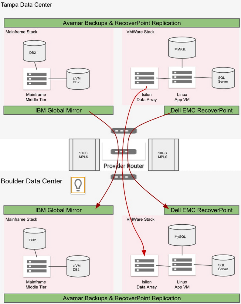
Some of the most desirable applications to move into the cloud are ones that run on proprietary platforms such as VMware, connected to enterprise storage arrays. But because those applications are often mission-critical, they can also be the most challenging—especially if they have demanding disaster recovery time objectives (RTOs) and recovery point objectives (RPOs), and are configured using an isolated, “bubble” network. We want to help you find the right DR solution for your cloud projects quickly. In this blog post, we review the basic concepts involved in doing DR in the cloud. Then, we present an example use case of a fictionalized customer, Acme Corporation. Acme has a bubble network and very short RPO/RTO of two hours and four hours, respectively. We then evaluate several popular DR solutions that meet their requirements, and show you how to deploy them in Google Cloud.Getting to know Acme Corp.Acme Corp. is your classic legacy enterprise, and runs all of its applications on VMware and mainframe infrastructure in two on-premises data centers—one primary and the other for remote DR. Acme wants to move into Google Cloud to modernize infrastructure and reduce costs. As such, it needs to find a robust disaster recovery solution for  a Google Cloud environment that can achieve its tight RPO/RTO requirements.Further complicating the design, Acme practices DR with a bubble or “isolation network,” where the VMs in primary and DR sites have the same set of private IPs. This bubble network requirement brings additional challenges to the disaster recovery architecture in the cloud. The following diagram illustrates Acme’s different stacks of system, application and data, as well as how they perform backups and disaster recovery in their current on-prem data center environment.Figure 1: On-prem network and disaster recoveryFrom the diagram, you can see the details of Acme’s setup:For its current DR strategy, Acme conducts block-level data replication for all the data and resources in its on-prem data centers. Its overall RPO is two hours, and the RTO is four hours.Acme has 500 VMs for Windows and 3000 servers in total. Avamar can take daily backups of VMs, OSs, persistent disks and databases. Data is replicated to the DR data center. These backups are not used for DR.IBM Global Mirror conducts block-level data replication for DR for the IBM mainframe stack, including the mainframe middle tier, the DB2 database (configuration table) and z/VM DB2 database (core server).Isilon (i.e., PowerScale) SyncIQ conducts data replication for DR for Acme’s Isilon file data.EMC RecoverPoint conducts data replication for DR for the VMware stack, including VMware VM-based applications, SQL Server, and MySQL databases.By migrating to Google Cloud, the following changes apply to Acme’s system and applications:Both IBM DB2 and z/VM DB2 are migrated into Compute Engine-based “Linux/Unix/Windows”, LUW DB2IBM Global Mirror is not applicable in the Google Cloud environment anymoreEMC RecoverPoint is not available in the GCP environmentIsilon, now called PowerScale, is now available as a SaaS solution in the Google Cloud environmentIn addition, when it moved to Google Cloud, Acme adopted Apigee to orchestrate its web services, and that environment also needs to be protected. Taken together, there are three major requirements that will determine the DR solution that we design for Acme’s systems running in Google Cloud:Two-hour RPO requirement for production systemsSupport for the current bubble network design and implementation, to avoid a major system and application rewriteThe ability to orchestrate the disk remount for thousands of VMs, each of which may have up to 24 disks mountedA solution for the Apigee stackBased on our team’s experience implementing this DR architecture for a real-world customer, we created this example DR solution for Acme. We divide Acme’s systems and applications in GCP into the following stacks:Apigee, the Google-provided managed service. PowerScale (Isilon), running as a third party managed service in GCP.Databases and applications running in VMs with a maximum of two-hour RPO. Production applications running in VMs with data that don’t need to meet 2-hour RPO. Exploring potential solutionsWith those requirements in mind, we explored the following approaches. Native regional DR and snapshotsGCP native regional DR via architecture design works well for cloud-native systems that are designed with HA and DR requirements. However, for Acme, this solution would require major application architecture changes. Also, this solution won’t work with bubble network constraints because IP conflicts prevent real-time VM-level traffic between the primary and DR regions.Further, this architecture relies on taking incremental snapshots for each disk. For Acme, this is unworkable: With its 3,000 servers, it will take great effort to make sure that each disk is restored from its snapshots and then mounted to the restored VM in the right order. This becomes almost impossible to manage without a multi-threading orchestration tool to automate this process under the situation of disaster recovery. We decide not to go down this path. ActifioAnother promising solution is Actifio GO, a Backup and DRService platform available on Google Cloud. It delivers backup, disaster recovery, migration to Google Cloud, database and VM cloning for test data management (TDM), and ransomware recovery, as well as enabling analytics with BigQuery. Actifio GO’s service architecture comprises several components that work in unison to deliver the service. It also supports our bubble network requirement. The following diagram illustrates the design of the Actifio DR solution for Acme.Figure 2: Actifio disaster recovery for a network with identical IPsTo support Acme’s bubble network and keep the same IP addresses in the DR region, we need the same set of Acme VPC and network settings in Acme’s Google Cloud DR region. Therefore, we have “acme-transit-DR-vpc” in the DR region mirror the “acme-transit-vpc” in the primary Google Cloud region. This is further made possible by the fact that Actifio uses Google Cloud Storage—more on that later. Actifio Global Manager (AGM) is hosted in Google’s network. AGM needs to establish VPC peering with Acme’ VPC, so it can deploy Actifio Sky into Acme’s network to work as the agents for backup and recovery. The bubble network prevents us from deploying Actifio Sky into “acme-transit-vpc” and “acme-transit-DR-vpc” because AGM will peer with two VPCs with the IP ranges. Therefore, we create separate VPCs in each region, “sky-vpc-east” and “sky-vpc-central”, to run Actifio Sky.In this configuration, since VPC peering is non-transitive (no more than two VPCs connected sequentially), AGM VPCs don’t see the peering details of individual SKY VPCs with DR and Primary VPC CIDR ranges. Thus, the CIDR ranges for “sky-vpc-east” and “sky-vpc-central” need to be carefully selected because they need to peer with AGM VPC, “acme-transit-vpc” and “acme-transit-DR-vpc” respectively. Actifio GO uses Cloud Storage to store its backup files. For local region backup only, we can use single-region Cloud Storage in the same region. For disaster recovery, we can use a Cloud Storage bucket in the DR region, improving performance. Actifio also can work with multi-region Cloud Storage buckets for high availability. Because Cloud Storage is used mainly for disaster recovery here, we recommended using either near-line or cold-line storage classes.For general VMs where Actifio cannot meet the required RPO/RTO, Acme can migrate those on-prem VMs into Google Cloud VMware Engine, as described in the next section.Google Cloud VMware Engine and ZertoGoogle Cloud VMware Engine is a fully managed service running the VMware platform natively on Google Cloud bare metal infrastructure in Google Cloud locations and fully integrating with the rest of Google Cloud. To meet Acme’s demanding RTO/RPO requirements for its most demanding applications, we explore coupling it with Zerto, a scalable replication platform that virtually eliminates data loss and downtime to ensure continuous availability. Google Cloud VMware Engine also works for mainframe applications. For these applications, the migrated OpenFrame instance can also run on VMware VMs in Google Cloud VMware Engine if needed. Then, we achieve cross-region DR using two Google VMware Private Clouds mirroring VMs using Zerto replication and restoration. Designed correctly, the RPO/RTO for this solution can be very small (RPO < 30 mins), easily satisfying Acme’s RPO/RTO (2 hours/4 hours) requirements. The following two diagrams, replication and recovery, illustrate Acme’s Google Cloud VMware Engine + Zerto disaster recovery solution.Figure 3: Google Cloud VMware Engine + Zerto Data Replication for a network with identical IPsFigure 4: Google Cloud VMware Engine + Zerto Data Recovery for a network with identical IPsThe network configuration happens mainly on the Google Cloud VMware Engine level. Google Cloud VMware Engine uses Private Service Access connection to peer with the Acme VPC to bring its VPC into the Acme network. Because Acme uses a bubble network with identical IPs in the DR region, we configure “acme-transit-vpc” in the Primary region and “acme-transit-DR-vpc” in the DR region. Also, we have “Workload Subnets” with the same CIDRs in both Google Cloud VMware Engine VPCs. Under normal circumstances, both Google Cloud VMware Engine VPCs are peered with the “acme-transit-vpc” VPC. Also, the route to the “Workload Subnets” in the GCVE-central (DR region) is turned off, so that there is no IP conflict. We configure Zerto to replicate data from GCVE-primary to GCVE-dr via the peered network connection through “acme-transit-vpc”. In the event of a disaster in the primary Google Cloud region, the peered connection between GCVE-dr and “acme-transit-vpc” is manually disconnected. Then GCVE-dr is peered with the “acme-transit-DR-vpc”. Also, the route to the “Workload Subnets” in the GCVE-dr region is turned on. Then, Zerto restores the replicated VMs, data and applications into the “Workload Subnets”. You can find detailed instructions on how to set up the Google Cloud VMware Engine VPC and configure the network connections with an existing Google Cloud VPC in the following document: Setting up private services access. PowerScale (Isilon) To protect Acme’s PowerScale (Isilon) array, we use Dell EMC Powerscale SyncIQ to replicate data between PowerScale nodes across regions via multi-NICs VM that reside in the primary region but which have a secondary Network Interface (NIC) for the bubble network in the DR region.Figure 5: PowerScale (Isilon) Disaster RecoveryApigeeLast but not least, we need to protect Acme’s Apigee environment, which it uses for microservices deployed in Google Cloud. Apigee offers a globally redundant level of data centers where traffic can be serviced in multiple regions or countries so that if an entire region goes offline, the data still flows. As shown in the diagram below, with a multi-region Apigee license in place, network traffic can be automatically routed to the disaster recovery region.Figure 6: Apigee Disaster RecoverySummaryIt’s a complicated setup, but that’s not unusual for enterprises looking to migrate a variety of demanding applications to the cloud. You can see our final Acme disaster recovery architecture in the following diagram, with current on-prem DR architecture on the left and Google Cloud DR architecture on the right.Figure 7: The Disaster Recovery Architecture OverviewTo learn more about how to configure your DR environment for Google Cloud, check out the following documentation: Actifio GO Documentation Library and Configuring disaster recovery using Zerto. Alternatively, please reach out to us—we’d be happy to explore your particular use case with you! Special thanks to our former colleague Jianhe Liao for his contributions to this blog post.Related ArticleNew in Google Cloud VMware Engine: autoscaling, Mumbai expansion, etc.A review of the latest updates to Google Cloud VMware Engine.Read Article
Quelle: Google Cloud Platform

PyTorch on Google Cloud: How to deploy PyTorch models on Vertex AI

This article is the next step in the series of PyTorch on Google Cloud using Vertex AI. In the preceding article, we fine-tuned a Hugging Face Transformers model for a sentiment classification task using PyTorch on Vertex Training service. In this post, we show how to deploy a PyTorch model on the Vertex Prediction service for serving predictions from trained model artifacts. Now let’s walk through the deployment of a Pytorch model using TorchServe as a custom container by deploying the model artifacts to a Vertex Endpoint. You can find the accompanying code for this blog post on the GitHub repository and the Jupyter Notebook.Deploying a PyTorch Model on Vertex Prediction ServiceVertex Prediction service is Google Cloud’s managed model serving platform. As a managed service, the platform handles infrastructure setup, maintenance, and management. Vertex Prediction supports both CPU and GPU inferencing and offers a selection of n1-standard machine shapes in Compute Engine, letting you customize the scale unit to fit your requirements. Vertex Prediction service is the most effective way to deploy your models to serve predictions for the following reasons:Simple: Vertex Prediction service simplifies model service with pre-built containers for prediction that requires you to only specify where you store your model artifacts. Flexible: With custom containers, Vertex Prediction offers flexibility by lowering the abstraction level so that you can choose whichever ML framework, model server, preprocessing, and post-processing that you need.Assistive: Built-in tooling to track performance of models and explain or understand predictions.TorchServe is the recommended framework to deploy PyTorch models in production. TorchServe’s CLI makes it easy to deploy a PyTorch model locally or can be packaged as a container that can be scaled out by the Vertex Prediction service. The custom container capability of Vertex Prediction provides a flexible way to define the environment where the TorchServe model server is run. In this blog post, we deploy a container running a TorchServe model server on the Vertex Prediction service to serve predictions from a fine-tuned transformer model from Hugging Face for the sentiment classification task. You can then send input requests with text to a Vertex Endpoint to classify sentiment as positive or negative.Figure 1. Serving with custom containers on Vertex Prediction serviceFollowing are the steps to deploy a PyTorch model on Vertex Prediction:Download the trained model artifacts.Package the trained model artifacts including default or custom handlers by creating an archive file using the Torch Model Archiver tool.Build a custom container (Docker) compatible with the Vertex Prediction service to serve the model using TorchServe.Upload the model with the custom container image as a Vertex Model resource.Create a Vertex Endpoint and deploy the model resource to the endpoint to serve predictions.1. Download the trained model artifactsModel artifacts are created by the training application code that are required to serve predictions. TorchServe expects model artifacts to be in either a saved model binary (.bin) format or a traced model (.pth or .pt) format. In the previous post, we trained a Hugging Face Transformer model on the Vertex Training service and saved the model as a model binary (.bin) by calling the .save_model() method and then saved the model artifacts to a Cloud Storage bucket.Based on the training job name, you can get the location of model artifacts from Vertex Training using the Cloud Console or gcloud ai custom-jobs describe command and then download the artifacts from the Cloud Storage bucket.2. Create a custom model handler to handle prediction requestsTorchServe uses a base handler module to pre-process the input before being fed to the model or post-process the model output before sending the prediction response. TorchServe provides default handlers for common use cases such as image classification, object detection, segmentation and text classification. For the sentiment analysis task, we will create a custom handler because the input text needs to be tokenized using the same tokenizer used at the training time to avoid the training-serving skew. The custom handler presented here does the following:Pre-process the input text  before sending it to the model for inference using the same Hugging Face Transformers Tokenizer class used during trainingInvoke the model for inferencePost-process output from the model before sending back a response3. Create custom container image with TorchServe to serve predictionsWhen deploying a PyTorch model on the Vertex Prediction service, you must use a custom container image that runs a HTTP server, such as TorchServe in this case. The custom container image must meet the requirements to be compatible with the Vertex Prediction service. We create a Dockerfile with TorchServe as the base image that meets custom container image requirements and performs the following steps:Install dependencies required for the custom handler to process the model inference requests. For e.g. transformers package in the use case.Copy trained model artifacts to /home/model-server/ directory of the container image. We assume model artifacts are available when the image is built. In the notebook, we download the trained model artifacts from the Cloud Storage bucket saved as part of hyperparameter tuning trials.Add the custom handler script to /home/model-server/ directory of the container image.Create /home/model-server/config.properties to define the serving configuration such as health check and prediction listener portsRun the Torch Model Archiver tool to create a model archive file from the files copied into the image /home/model-server/. The model archive is saved in the /home/model-server/model-store/ with name same as <model-name>.marLaunch Torchserve HTTP server to enable serving of the model referencing the configuration properties and the model archive fileLet’s understand the functionality of TorchServe and Torch Model Archiver tools in these steps.Torch Model ArchiverTorchserve provides a model archive utility to package a PyTorch model for deployment and the resulting model archive file is used by torchserve at serving time. Following is the torch-model-archiver command added in Dockerfile to generate a model archive file for the text classification model:Model Binary (–serialized-file parameter): Model binary is the serialized Pytorch model that can either be the saved model binary (.bin) file or a traced model (.pth) file generated using TorchScript – Torch Just In Time (JIT) compiler. In this example we will use the saved model binary generated in the previous post by fine-tuning a pre-trained Hugging Face Transformer model.NOTE: JIT compiler trace may have some device-dependent operations in the output. So it is often a good practice to generate the trace in the same environment where the model will be deployed.Model Handler (–handler parameter): Model handler can be TorchServe’s default handlers or path to a python file to handle custom TorchServe inference logic that can pre-process model inputs or post-process model outputs. We defined a custom handler script in the previous section of this post.Extra files (–extra-files parameter): Extra files allow you to package additional files referenced by the model handler. For example, a few of the files referred in the command are:index_to_name.json: In the custom handler defined earlier, the post-processing step uses an index-to-name JSON file to map prediction target indexes to human-readable labelsconfig.json: Required for AutoModelForSequenceClassification.from_pretrained method to load the modelvocab.txt: vocab files used by the tokenizerTorchServeTorchServe wraps PyTorch models into a set of REST APIs served by a HTTP web server. Adding the torchserve command to the CMD or ENTRYPOINT of the custom container launches this server. In this article we will only explore prediction and health check APIs. The Explainable AI API for PyTorch models on Vertex endpoints is currently supported only for tabular data.TorchServe Config (–ts-configparameter):  TorchServe config allows you to customize the inference address and management ports. We also configure service_envelop field to json to indicate the expected input format for TorchServe. Refer to TorchServe documentation to configure other parameters. We create a config.properties file and pass it as TorchServe config.Model Store (–model-storeparameter): Model store location from where local or default models can be loadedModel Archive (–modelsparameter):  Models to be loaded by TorchServe using [model_name=]model_locationformat. Model location is the model archive file in the model store.4. Build and push the custom container imageRun the following command to build the container image based on the Dockerfile and tag it with a name compatible with your Container Registry repository:Before pushing the image to the Container Registry, you can test the docker image locally by sending input requests to a local TorchServe deployment running inside docker.To run the container image as a container locally, run the following command:To send the container’s server a health check, run the following command:This request uses a test sentence. If successful, the server returns the prediction in the following format:After the response is verified, it confirms that the custom handler, model packaging and torchserve config are working as expected. You can stop the TorchServe local server by stopping the  container.Now push the custom container image to the Container Registry, which will be deployed to the Vertex Endpoint in the next step.NOTE: You can also build and push the custom container image to the Artifact Registry repository instead of the Container Registry repository.5. Deploying the serving container to Vertex Endpoint We have packaged the model and built the serving container image. The next step is to deploy it to a Vertex Endpoint. A model must be deployed to an endpoint before it can be used to serve online predictions. Deploying a model associates physical resources with the model so it can serve online predictions with low latency. We use Vertex SDK for Python to upload the model and deploy it to an endpoint. Following steps are applicable to any model trained either on Vertex Training service or elsewhere such as on-prem.Upload modelWe upload the model artifacts to Vertex AI and create a Model resource for the deployment. In this example the artifact is the serving container image URI. Notice that the predict and health routes (mandatory routes) and container port(s) are also specified at this step.After the model is uploaded, you can view the model in the Models page on the Google Cloud Console under the Vertex AI section.Figure 2. Models page on Google Cloud console under the Vertex AI sectionCreate endpointCreate a service endpoint to deploy one or more models. An endpoint provides a service URL where the prediction requests are sent. You can skip this step if you are deploying the model to an existing endpoint.After the endpoint is created, you can view the endpoint in the Endpoints page on the Google Cloud Console under the Vertex AI section.Figure 3. Endpoints page on Google Cloud console under the Vertex AI sectionDeploy the model to endpointThe final step is deploying the model to an endpoint. The deploy method provides the interface to specify the endpoint where the model is deployed and compute parameters including machine type, scaling minimum and maximum replica counts, and traffic split.After deploying the model to the endpoint, you can manage and monitor the deployed models from the Endpoints page on the Google Cloud Console under the Vertex AI section.Figure 4. Manage and monitor models deployed on Endpoint from Google Cloud console under the Vertex AI sectionTest the deploymentNow that the model is deployed, we can use the endpoint.predict() method to send base64 encoded text to the prediction request and get the predicted sentiment in response.Alternatively, you can also call the Vertex Endpoint to make predictions using the gcloud beta ai endpoints predict command. Refer to the Jupyter Notebook for complete code.Cleaning up the environmentAfter you are done experimenting, you can either stop or delete the Notebooks instance. Delete the Notebook instance to prevent any further charges. If you want to save your work, you can choose to stop the instance insteadTo clean up all Google Cloud resources created in this post and the previous post, you can delete the individual resources created:Training JobsModelEndpointCloud Storage BucketContainer ImagesFollow the Cleaning Up section in the Jupyter Notebook to delete the individual resources.What’s next?Continuing from the training and hyperparameter tuning of the PyTorch based text classification model on Vertex AI, we showed deployment of the PyTorch model on Vertex Prediction service. We deployed a custom container running a TorchServe model server on the Vertex Prediction service to serve predictions from the trained model artifacts. As the next steps, you can work through this example on Vertex AI or perhaps deploy one of your own PyTorch models.ReferencesDeploying models on Vertex Prediction serviceCustom container requirements for prediction | Vertex AIGitHub repository with code and accompanying notebookIn the next article of this series, we will show how you can orchestrate a machine learning workflow using Vertex Pipelines to tie together the individual steps which we have seen so far, i.e. training, hyperparameter tuning and deployment of a PyTorch model. This will lay the foundation for CI/CD (Continuous Integration / Continuous Delivery) for machine learning models on the Google Cloud platform.Stay tuned. Thank you for reading! Have a question or want to chat? Find authors here – Rajesh [Twitter | LinkedIn] and Vaibhav [LinkedIn].Thanks to Karl Weinmeister and Jordan Totten for helping and reviewing the post.
Quelle: Google Cloud Platform

Amazon MQ unterstützt jetzt RabbitMQ Version 3.8.22

Sie können jetzt RabbitMQ-3.8.22-Broker in Amazon MQ starten. Diese Version enthält eine Lösung für ein Problem mit Warteschlangen, die TTL (Time to Live) pro Nachricht verwenden, das in der zuvor unterstützten Version RabbitMQ 3.8.17 identifiziert wurde und wir empfehlen ein Upgrade auf RabbitMQ 3.8.22.
Quelle: aws.amazon.com

Amazon Elasticsearch Service ist jetzt Amazon OpenSearch Service; es fügt Support für OpenSearch 1.0 hinzu

Amazon Elasticsearch Service hat einen neuen Namen: Amazon OpenSearch Service. Diese zuvor hier angekündigte Änderung fällt mit der Hinzufügung des Supports für OpenSearch 1.0 zusammen. Sie können jetzt sowohl OpenSearch- als auch Elasticsearch-Cluster (bis Version 7.10) auf Amazon OpenSearch Service ausführen und skalieren und alle Vorteile nutzen, die Sie bisher von Amazon Elasticsearch Service genossen haben.
Quelle: aws.amazon.com

Amazon OpenSearch Service (Nachfolger von Amazon Elasticsearch Service) unterstützt jetzt Indextransformationen

Amazon OpenSearch Service (Nachfolger von Amazon Elasticsearch Service) unterstützt jetzt Indextransformationen, mit denen Kunden wichtige Informationen aus großen Datensätzen extrahieren und zusammengefasste Ansichten in neuen Indizes speichern können. Kunden können aus dem neuen Übersichtsindex neue Erkenntnisse ableiten, weiter analysieren und Trends visualisieren.
Quelle: aws.amazon.com